Scaling Data Center connectivity

The AI supercycle is transforming the communications industry, with data center connectivity at its core. Data center construction is driving the need for new connectivity in new geographies while capacity demands from AI and cloud providers drive the need for interconnectivity that exceeds petabits per second across multiple fiber pairs.
Data center facilities are often separated by long-haul distances of more than 1,000 kilometers and require DWDM optical transport networks that combine ultra-low power-per-bit efficiency with operational simplicity. Features such as plug-and-play integration, effortless scalability, rapid deployment and fast service activation are essential for meeting these demands.
Optical line systems are the foundation for all connectivity
One major part of the optical transport network solution is the optical line system. Line systems provide important functions such as:
- Add/drop multiplexers for grooming multiple wavelengths into a single fiber. There are various options, including fixed add/drop, colorless add/drop and colorless, directionless and contentionless add/drop. Think of these as multiple on-ramps for data highways.
- Wavelength selective switches (WSSs) for enabling or blocking specific wavelengths or groups of wavelengths, and for dynamic optical power equalization of wavelengths. Think of WSSs as traffic controllers for light.
- Booster amplification for amplifying the wavelengths in the transmit direction into the line fiber after the wavelengths have passed the add/drop and WSS stages.
- Preamplification for amplifying wavelengths in the receiving direction, coming in from the line fiber.
- Optical channel monitoring (OCM) for reading out individual wavelength optical power at various stages of the signal path for further processing.
- Amplified spontaneous emission (ASE) noise for injecting broadband noise into unused wavelength spectrum to help suppress power transients, especially for combined C- and L-band transmission.
- An optical time-domain reflectometer (OTDR) for measuring fiber quality and fiber loss, along with the distance to a fiber cut in fault scenarios.
- An optical supervisory channel (OSC) that enables management communication between nodes along the optical path—for example, to intermediate inline amplification sites.
- Inline amplification (ILA) sites that reamplify all wavelengths along the path.
To create a full line system for C- and L-band transmission, we need to connect these components and technologies together. These line system building blocks are modular and help telecommunication providers scale their networks in a granular way as traffic demand arises. For example, ASE and L-band amplifiers can be added when the network expands beyond the C-band. The OTDR might not be needed for every fiber path. Figure 1 is a functional drawing of such a line system with individual sleds and their patch cabling.
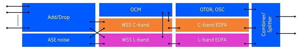
Figure 1: Building blocks of a modular line system
Integrated blade design for operational efficiency
Given the substantial data center interconnect (DCI) capacity requirements, where multiple fibers with fully loaded C+L band capacity are required on day one, it is now rational to integrate all of these key line system technologies into a single blade (Figure 2). This integration drops the need for additional sleds and intra-system fiber patch cabling, which leads to faster deployment and simplified operations. As a result, a complete C+L band line system can be deployed with a single blade per fiber.
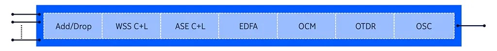
Figure 2: Highly integrated C+L band terminal
One of the key enablers for this highly integrated approach is the latest innovation in WSS technology. Devices today include a 1x66 twin WSS component that combines C- and L-band spectrum and 66 add/drop ports. The combination of 66 ports and the 9.6 THz spectrum is particularly well-suited for 150 GHz spaced 800G ZR/ZR+ channels – 32x150 GHz = 4.8 THz in the C-band and 32x150 GHz = 4.8 THz in the L-band. While optimized for 150 GHz spacing, the WSS can be tuned to support any passband and any coherent technology including 400G ZR+, future 1.6 Tb/s pluggables as well as 1.2 Tb/s and future 3.2 Tb/s embedded technologies.
The same highly integrated approach can be applied to ILA systems, where C+L band amplifiers are integrated for both the west and east directions, and OSC, OTDR and dynamic gain equalization (DGE) components can be integrated into a single blade. This configuration allows one blade to serve both fiber directions at ILA sites. We can now build a more simplified multi-rail end-to-end optical transport network for greater operational efficiency compared to the modular system approach.
Figure 3 shows a schematic representation of an eight fiber pair line system deployment, providing connectivity with a total capacity of 409.6 Tb/s, all within just 16 rack units per site. This represents a space reduction of two-thirds compared to the previous modular approach. The design allows for scalable deployment, with a one-to-one mapping of blades to fibers.
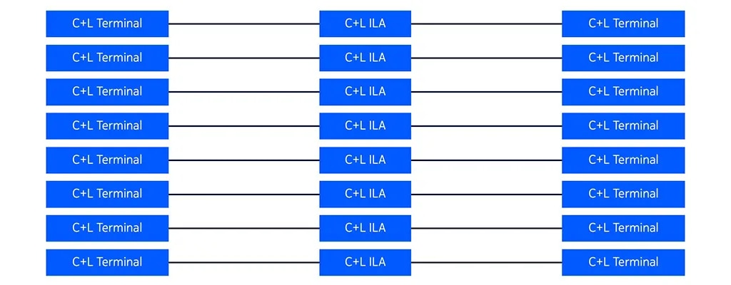
Figure 3: Open line system with eight fiber rails
Coherent transceiver evolution lowers power per bit
Over the last 20 years, optical transceiver technology has cut power-per-bit from 5 W/Gb to 0.04 W/Gb with the latest 800G ZR/ZR+ coherent pluggable technology. This is a more than 100-fold reduction. Due to the form factor of these pluggable transceivers, they are now also suitable for deployment directly in third-party routers and switches, thereby dropping the requirement for a separate DWDM transponder.
Development cycles for the 800G generation of routers and switches are now also perfectly aligned with the latest 800G coherent optical transceivers and the latest 800G routers and switches support the deployment of a large number of 30 W 800G ZR/ZR+ pluggable transceivers.
Putting it all together for the lowest TCO
We are now able to deploy a highly compact and efficient C+L band optical transmission system that minimizes power consumption per bit while also improving operational efficiency (Figure 4). This design uses a single blade per fiber at terminal sites and a single blade per fiber at ILA sites, enabling the connection of 800G ZR/ZR+ transceivers in both the C- and L-bands at any add/drop port.
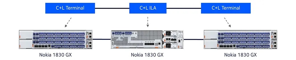
Figure 4: Nokia 1830 GX implementation
The Nokia 1830 GX hyperscale line system enables the rapid deployment of DCI networks over metro and long-haul distances, all while supporting minimal power per bit and automated optical power balancing. Modern native APIs enable fast turn up and network integration. Earlier this year, the solution earned recognition from the industry as a standout innovation.
This hyperscale interconnect solution is designed not only for AI cluster connectivity, but also for telecommunication providers, wholesale businesses, internet exchange points (IXPs), content delivery networks (CDNs), or any operator that requires high-capacity C+L band connectivity between data centers, optimized for maximum fiber utilization, minimal power consumption and superior operational efficiency.
Further evolution steps of this architecture are just around the corner, and an even higher level of integration of line system functionalities is being developed. Stay tuned for the next wave of DCI innovation.