How 5G synchronization impacts mobile transport provider networks

Two years ago, I wrote about the changes that mobile network operators (MNOs) would be requesting of mobile transport providers (MTPs) to support new 5G services and how MTPs should prepare their networks. Today, cell sites have moved from 1G to 10G services, making the 10G the new default for Ethernet virtual connections (EVCs). This has a significant impact on the way MTPs design and build their networks to support quality of service (QoS) parameters, especially buffering.
This post covers the new set of synchronization requirements that 5G brings and how MTPs should evolve their networks to deliver services that meet the needs of their MNO customers.
New synchronization requirements for 5G
Synchronization is at the heart of mobile networks because it helps to enable critical RAN functions such as handovers so that devices can move freely around the network. Older generations of mobile networks used FDD technology focused only on frequency synchronization. However, new TDD spectrum and radio features from 3GPP, including carrier aggregation, add time synchronization as a requirement to 5G mobile networks.
Most of the allocated 5G spectrum bands use TDD technology, which requires frequency and phase/time synchronization. With better coordination among cell sites, MNOs can use available spectrum resources more efficiently, increase bandwidth, improve handoff between cells and support carrier aggregation. Frequency and time synchronization are both as important as power in today’s mobile networks.
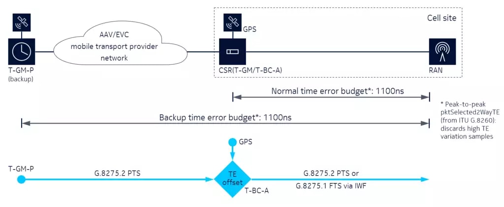
5G imposes more stringent reliability requirements on the network because the loss of the GNSS signal can impact radios within a few hours. This means the network needs a reliable backup synchronization source. In many cases, this backup will come from a site other than the one where the radios are located. The backup will use the MTP’s network to transport the synchronization source.
Some MNOs will rely on MTPs to “transparently” transport the backup clock reference across their network. But the network’s nodes may not be Precision Time Protocol (PTP) aware from their centralized location to each access site. Emerging technologies such as Partial Timing Support (PTS) and Assisted Partial Timing Support (APTS) can meet the transport requirement when Full Timing Support (FTS) is not a viable option.
Here is a quick comparison between FTS and PTS:
FTS: ITU G.8275.1 telecom profile with Ethernet encapsulation

- All intermediate nodes on the PTP path operate as boundary clocks or transparent clocks.
- PTP/Ethernet with Ethernet multicast mode.
- Reference model and time error (TE) budget allocations are available. They provide predictable accuracy (very low phase error between boundary clocks) and scalability.
PTS: ITU G.8275.2 telecom profile with IP/UDP encapsulation

- Most intermediate nodes do not support PTP. There may be some boundary clocks but this is not expected.
- PTP/UDP/IP/Ethernet with IP unicast mode.
- Accurate planning and testing is needed for small indoor last-mile deployments.
- PTP is often used with APTS where there is a GNSS receiver at the telecom time slave clock (T-TSC) location).
Based on this comparison of FTS and PTS, and the current implementation where MTPs provide a “transparent L2 tunnel” to MNOs, APTS provides the simplest solution to the synchronization requirement.
APTS overview

APTS allows MNOs to use a local GNSS reference for normal operation and then fall back on G.8275.2 PTP across the MTP’s network as a backup. If the GNSS source fails, the PTP backup is automatically used to keep the clocks synchronized and stable. While GNSS has lock, the G.8275.2 PTP backup is monitored to compute any constant time error (cTE) from the network. This error would be caused by asymmetric delays across the network. Some asymmetric delay will depend on the specific hardware in the network path and some will depend on the symmetry of the traffic loading. With the goal to keep phase/time as accurate as possible (and avoid any transients), the last cTE calculated before the GNSS failure is applied as a correction when the MNO switches to the backup. It is assumed that the measured TE remains constant but this cannot be guaranteed.
MTPs must comply with the following ITU-T 8271.2 APTS requirements on their EVC/Alternative Access Vendor (AAV) services to keep clocks synchronized when the backup is used:
- The network limit value and metric processing parameters that apply for APTS packet networks are as follows:
- Peak-to-peak pktSelected2wayTE = < 1100 ns
- Selection window = 200 s
- Selection percentage = 0.25 percent
- Selection method = percentile average packet selection
- Window step size = < 20 s
- There is no way to measure and remove a cTE for (non-assisted) PTS packet networks, so the first metric changes from peak-to-peak to an absolute limit. The remaining requirements are the same:
- max | pktSelected2wayTE | < 1100 ns
Test report: APTS across MTP networks
We replicated a few of our MTP and MNO customer networks and ran multiple scenarios (varying hop counts, total latency, traffic load and traffic load ramp) where the MTP transports the APTS signal though a 10G EVC service across a 10/100G MTP network towards the MNO.

Here are some key findings based on the results:
- A network of up to six Nokia 7x50 series routers can meet the PTS requirements of G.8271.1 in almost all conditions.
- Individual nodes (based on switch fabric versus fabric-less) have different delay asymmetry from line to fabric and fabric to line:
- This is not an issue for the APTS network limits (asymmetry is not a concern).
- An understanding of the individual cards in use may be required for PTS.
- No special configuration is needed on the MTP’s network, aside from setting the proper QoS for the synchronization packets.
Use case: Static load
As an initial test, we simulated a simple condition of static loading across the network links. As shown in the graph below, for the worst-case scenario (Router #6), the network met both the PTS and APTS network limits, remaining below the 1.1 µs TE threshold.

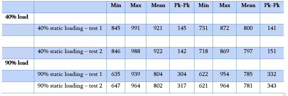
We ran this static test multiple times and with two different loading levels: 40% and 90%. The results are summarized in the table below. In all these tests, both the PTS and APTS limits were met.

Note: The TE is the difference between the original grandmaster clock signal and the sync signal for the device under test. This value is better when it is closer to 0.
Use Case: Traffic ramp
For this use case, we slowly increased the traffic across the network from 20 percent to 80 percent in the forward direction and from 10 percent to 50 percent in the reverse direction over six hours. We then slowly reduced the traffic over another six hours. This provides some representation of the changes to loading that can occur on a network during a day. As shown in the graph below, there is a small change in the pktSel2WayTE because of a pipelining effect for changes to the delays of the PTP messages. However, the network remained solidly within the performance requirements.

Full Timing Support
As a comparison, we reconfigured the network to have all the network elements act as PTP boundary clocks to create an FTS network environment. As expected, the performance was consistent and immune to all variations in traffic load that were applied from 0 percent up to 80 percent on all network links. Note the change in vertical scale compared to the previous plots.

Conclusion and recommendations
Based on our experience with FTS, PTS/APTS and these results, we conclude that MTPs can successfully transport APTS “packets” in networks built using Nokia 7x50 router technology with a limit of six nodes. If more than six are required, we can extend the test. Furthermore, we conclude that:
- Despite our initial beliefs, “traffic load” has an acceptable impact across the AAV path
- Even with a reroute (assuming use of fast reroute) after the reroute on the path, the APTS will be able to recover
- If the network is not fully synchronized FTS, the MTP will have to rely on the MNO’s feedback or allocate test gear at the endpoints of the AAV (recommended)
- Assuming that acceptable generations of platforms and line cards are in use, no additional changes are needed on the MTP network
- As an option, the MTP may decide to provide a fully synchronized EVC (independent of the MNO), where the MTP can verify that the network-based timing input is at a good level. The MTP network will take the GNSS input and compare it with the input coming from the network. If there is a difference, the node sends an alarm.
Find out more
To learn more about the details of the technical report, please reach out to your Nokia representative or send me a direct email.


